Hi guys..
The basic principle of work

 Servo motor is can rotate from 0 to 180 degrees. In this project, servo is used to turn the ultrasonic sensor to left/right to record the distance of obstracles in side ways...
Geared DCmotors can also be used. The wheels are to be fitted to the shaft of the motor. The motor and castor wheel are screwed to chassis as shown below.
Arduino Code for the robot
//define pinmodes of declared pin numbers

This paper illustrates how to build an obstacle avoider wheeled ROBOT using ARDUINO UNO board!!
If you want to know more about arduino click HERE
Aim is to build an obstracle avoider robot using arduino uno!! There are many other blogs, instructables which have already described the design. The only speciality of this robot is that it uses only one SONAR sensor to check obstracles of all the directions!!
Components required to build obstracle avoider.
1) Arduino uno baord (buy)
2) Pair of DC motors and Wheels with screws and nuts (buy)
4)Castor Wheel (buy)
5)Robot Chassis (buy)
6)L293D motor driver board (buy)
7)9v batteries connectors and connecting wires
8)Servo motor (buy)

8)Servo motor (buy)
In this project, Arduino UNO with ATmega328P 8-bit microcontroller is used to control the activities of motors and sonar.
Arduino board is programmed using IDE provided by the arduino platform, the language used is c++ and IDE consists of libraries that are usefull for many sensors.
HC-SR04 sensor is used to find the exact distance of the obstracle. This economical sensor provides 2cm to 400cm of non-contact measurement functionality with a ranging accuracy that can reach up to 3mm.
HC-SR04 module includes an ultrasonic transmitter, a receiver and a control circuit.


The basic principle of work
- Using IO trigger for at least 10us high level signal
- The Module automatically sends eight 40 kHz and detect whether there is a pulse signal back
- If the signal back, through high level,time of high output IO duration is the time from sending ultrasonic to returning. Test distance=(high level timexvelocity of sound (340M/S) /2

 Servo motor is can rotate from 0 to 180 degrees. In this project, servo is used to turn the ultrasonic sensor to left/right to record the distance of obstracles in side ways...
Ultrasonic sensor is mounted on the servo as shown in the image. we can use screws/.nuts for this purpose, or a double sided tape can also be used.

Motor driver L293D ic is the most popular ic used for the two way control of dc motors. The L293D devices are quadruple high current half-H drivers. The L293D is designed Inputs to provide bidirectional drive currents of up to 600-mA at voltages from 4.5 V to 36 V.(datasheet)
Depending upon the availability of motors and requirements, we can use two motors with one castor wheel at the front or we can have four motors and wheels with two control boards(ld293d).
CHASSIS with wheels
 |
| Castor wheel |

 |
| Dc motors and wheels |
 |
| Assembled Vehicle |
Servo motor with ultrasonic sensor is mounted on chassis above castor wheel right at the centre of the chassis. Arduino uno and L293D driver are screwed on the chassis.
Batteries and connectors
Two 9v batteries are used in this project. One to drive arduino and the other for motor driver.
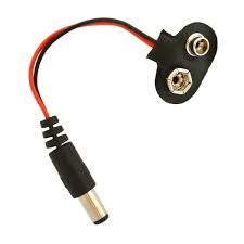 |
| Arduino power connector |

CONNECTIONS
1) Motors are connected to L293D driver. The control pins of the drivers are connected to 2,3,4,5 digital pins of arduino uno. And a 9v battery is used to turn on motor driver.
2)Servo motor-- Vcc and grnd pins are connected.
Signal pin is connected to digital pin 6.
3)Ultrasonic Sensor-- Vcc and Grnd pins are connected.
Trigger and echo are connected to 7 and 8 digital pins respectively.
Note: For both servo and ultrasonic sensor vcc must be +5v and arduino on baord supply can be used..
3.3v will not work for both components.
Arduino Code for the robot
/*
Obstacle detector SUV
* Ultrasonic sensor
* Unmanned vehicle for obstracle detection
created Mar 2016
by Rohith Udupa
*/
// Include the servo motor library
#include<Servo.h>
//define pin numbers used for motors
const int m1=2;
const int m2=3;
const int m3=4;
const int m4=5;
//define pin numbers used for ultrasonic sensor
const int trig=7;
const int echo=8;
//define name of the servo
Servo myservo;
long distance,left_dist, right_dist,t,t1,t2;
void setup() {
//define pin number for servo
myservo.attach(6);
pinMode(m1, OUTPUT);
pinMode(m2, OUTPUT);
pinMode(m3, OUTPUT);
pinMode(m4, OUTPUT);
pinMode(trig,OUTPUT);
pinMode(echo,INPUT);
//delay isto set up ultrasonic sensor for accurate measurement
delay(1000);
}
void loop() {
//calculation distance of obstracle in front ways
myservo.write(90);
digitalWrite(trig,LOW);
delayMicroseconds(2);
digitalWrite(trig,HIGH);
delayMicroseconds(10);
digitalWrite(trig,LOW);
t=pulseIn(echo,HIGH);
distance=(t/2)/29.1;
if(distance>6)//no obstracle
farward();
if(distance<=6)//there is an obstracle
{
halt();
delay(500);
findroute();//finds a route free of obstracle
}
}
void findroute()
{//to calculate distance of obstracle along side ways
myservo.write(0);//look right
delay(700);
digitalWrite(trig,LOW);
delayMicroseconds(2);
digitalWrite(trig,HIGH);
delayMicroseconds(10);
digitalWrite(trig,LOW);
t1=pulseIn(echo,HIGH);
right_dist=(t1/2)/29.1;
delay(600);
myservo.write(180);//look left
delay(700);
digitalWrite(trig,LOW);
delayMicroseconds(2);
digitalWrite(trig,HIGH);
delayMicroseconds(10);
digitalWrite(trig,LOW);
t2=pulseIn(echo,HIGH);
left_dist=(t2/2)/29.1;
delay(600);
myservo.write(90);
if(left_dist>right_dist & left_dist>13)
go_left();
if(right_dist>left_dist & right_dist>13)
go_right();
if(right_dist<=13 & left_dist<=13)
{backward();
delay(6000);
findroute();}
return 0;
}
void farward(void)
/*this code depends on the motor driver connection and pin assignment.
should be verified and tested before employment*/
{ digitalWrite(m1,LOW);
digitalWrite(m2,HIGH);
digitalWrite(m3,HIGH);
digitalWrite(m4,LOW);
return 0;}
void backward(void)
{ /*this code depends on the motor driver connection and pin assignment.
should be verified and tested before employment*/
digitalWrite(m2,LOW);
digitalWrite(m1,HIGH);
digitalWrite(m4,HIGH);
digitalWrite(m3,LOW);
return 0;}
void halt(void)
{ /*this code depends on the motor driver connection and pin assignment.
should be verified and tested before employment*/
digitalWrite(m2,LOW);
digitalWrite(m1,LOW);
digitalWrite(m4,LOW);
digitalWrite(m3,LOW);
return 0;
}
void go_left(void){
should be verified and tested before employment*/
digitalWrite(m2,LOW);
digitalWrite(m1,HIGH);
digitalWrite(m3,HIGH);
digitalWrite(m4,LOW);
delay(4000);
return 0;}
void go_right(void)
/*this code depends on the motor driver connection and pin assignment.
should be verified and tested before employment*/
{
digitalWrite(m2,HIGH);
digitalWrite(m1,LOW);
digitalWrite(m3,LOW);
digitalWrite(m4,HIGH);
delay(4000);
return 0;}
//code ends here
FINAL ROBOT MODEL


No comments:
Post a Comment